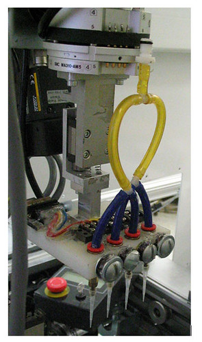
In 2005, as part of a graduate course on robotics, the team of Melissa Morris, John Morris, Thomas Kelly and I set about repurposing a JOT automation system (http://www.jotautomation.com/) which housed a four axis Hirata robot (http://www.hirata.it/) and was donated to FAU from Motorola. The system, pictured below, was originally used to print and apply barcodes in the battery compartment of cellular phones. The goal of the repurposing was to complete a project whereby the system would be converted into a pipetting robot, capable of dispensing liquids into 96-well microtiter plates. This was accomplished on an extremely lavish budget of $0.

While in service at Motorola, the robot originally functioned as follows:
- Phones were loaded onto custom aluminum pallets which would hold them in place.
- The pallet would roll down a conveyor into the robot where it would be electromechanically locked into a fixed position.
- The robot end effector inside of the system would use a vacuum to pick up a barcoded label from a label printer, apply it to a cell phone and then inspect the application with a camera which was mounted on the end effector.
- The pallet would be released, roll down to the next station and the process would be repeated.
The project broke down into two main technical challenges:
- How to modify the robot end effector to pipette liquid instead of handle printed labels?
- How to reprogram the robot to work with modified pallets that now held microtiter plates instead of cell phones?
The end effector
The modification to the end effector involved a bit of rather clever engineering. The liquid to be dispensed would be gravity fed to the pipette tips via a reservoir which was mounted on the end effector. The reservoir was connected to a plastic block, seen below, which had four vertical holes drilled through it for liquid to flow through. Inside of each hole sat a metallic ball and in front of each hole was a coiled copper wire which was connected to the robot’s power source. When power was applied to the coil, a magnetic field would be created that would pull the metal ball up from the bottom of the hole, essentially unplugging it and allowing the gravity fed liquid to begin flowing. By controlling the length of time the coils were energized, we could control how much liquid was dispensed. When power was cut, the ball would fall back to the bottom of the hole, thereby plugging it and preventing any additional liquid from flowing.
Reprogramming
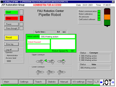
Unfortunately, when the robot was donated there was no accompanying documentation. After a bit of reverse engineering, we were able to work out how to reprogram the system with sample code left on the system’s embedded computer. This involved updating the GUI (seen below), setting proper parameters for the conveyors, and reprogramming the end effector to be at the correct coordinates in sync with the conveyor.
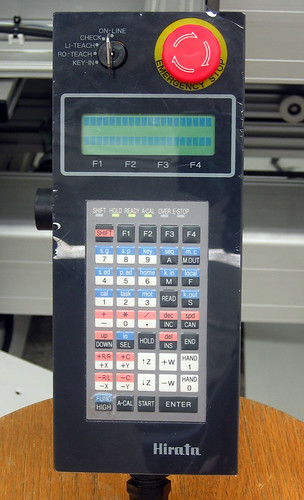
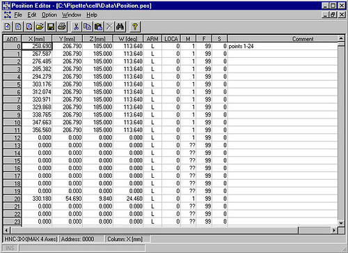
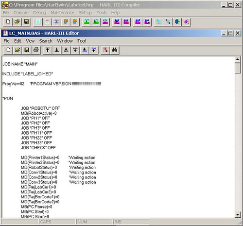
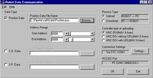
End effector coordinates were obtained by manually positioning the Hirata robot’s end effector using the control pendant. A palette would be run through the conveyor to the correct position at which time the end effector was moved to the pipetting locations within each microtiter plate and the X, Y, Z and W (end effector rotation) coordinates were recorded. These coordinates were then programmed into system memory using the Hirata HARL 3 compiler. Robot control pendant, Harl 3 coordinate editor, BASIC compilier and robot programming screens are seen below.
Ultimately, the system function as desired, as seen in the video below.


Pretty nice post. I just stumbled upon your blog and wanted to say that I have really enjoyed browsing your blog posts. In any case I’ll be subscribing to your feed and I hope you write again soon!